How to test ignition control module effectively is crucial for diagnosing and resolving automotive electrical issues. A malfunctioning ignition control module (ICM) can lead to a range of problems, from engine misfires to complete engine failure. This comprehensive guide provides a step-by-step approach to testing the ICM, covering everything from basic diagnostics to advanced troubleshooting techniques.
This guide delves into the intricacies of ignition control modules, from their fundamental functions to the specific diagnostic procedures required for effective testing. Understanding the symptoms, potential causes, and detailed testing methodologies is essential for a precise diagnosis and resolution.
Introduction to Ignition Control Modules
The ignition control module (ICM) is a crucial component in modern vehicles, acting as the brain of the ignition system. It precisely manages the timing and sequence of events during the ignition process, ensuring efficient and reliable engine operation. Without a properly functioning ICM, the engine may not start or run smoothly, potentially leading to performance issues and costly repairs.The ICM’s primary function is to regulate the spark timing and intensity for each cylinder.
This precise control optimizes fuel combustion, leading to better fuel efficiency and reduced emissions. It also monitors various sensor inputs to adjust the spark parameters in real-time, ensuring optimal performance under different operating conditions.
Components of an Ignition Control Module
The ICM typically comprises several key components, each playing a vital role in its overall functionality. These components are interconnected to create a complex system that manages the intricate spark timing requirements for the engine.
- Microprocessor Unit (MCU): This is the “brain” of the ICM, responsible for processing sensor data, calculating spark timing, and controlling the output signals. It constantly monitors inputs from various sensors to maintain optimal engine performance.
- Input Sensors: Various sensors provide real-time data to the MCU, including crankshaft position sensors, camshaft position sensors, and temperature sensors. These sensors measure critical engine parameters for accurate spark timing calculations.
- Output Devices: These components, such as spark plugs and coil packs, receive signals from the MCU to generate the necessary spark for combustion. Precise timing and voltage are crucial for optimal combustion efficiency.
- Power Supply and Grounding: The ICM requires a stable and consistent power supply from the vehicle’s electrical system. Grounding provides a return path for electrical signals. Proper grounding is essential for reliable operation and preventing electrical interference.
Types of Ignition Control Modules
ICMs vary across different vehicle makes and models due to factors like engine type, fuel type, and desired performance characteristics. These variations can impact the complexity and functionality of the module.
- Single-module systems: In simpler vehicles, the ICM might be a single unit controlling the entire ignition system. This is a more straightforward design, but its functionality may be limited.
- Modular systems: More advanced vehicles often feature modular designs with separate modules for specific engine components. This approach offers greater flexibility in controlling various aspects of the ignition system.
- Variations by Manufacturer: Different car manufacturers may utilize proprietary designs for their ICMs. These designs might incorporate specific features tailored to their vehicle lines.
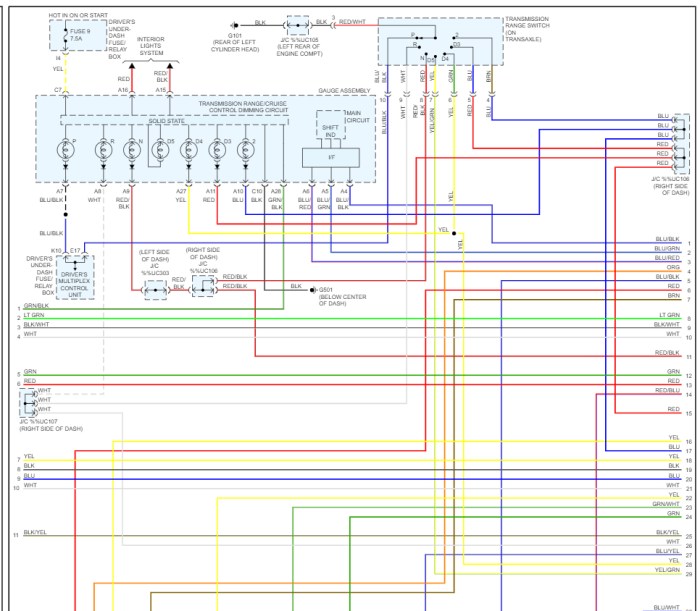
Basic ICM Circuit Diagram
The following diagram illustrates a simplified circuit for a basic ICM. Note that this is a simplified representation, and actual circuits can be significantly more complex.
+-----------------+     +--------+     +-------+
|    Battery      |-----| Ignition|-----|Coil Pack|
+-----------------+     +--------+     +-------+
          |                       |
          |                       |
          |                       |
          |                       |
          V                       V
          +--------+     +--------+
          |  MCU   |-----|  Sensor|
          +--------+     +--------+
          |       |     |    |
          |       |     |    |
          |       |     |    |  Spark Plugs
          +-------+     +-------+
This circuit diagram shows the basic flow of power and signals within the ICM.
The battery provides power to the module, which then processes signals from various sensors to control the spark timing and intensity for the coil packs and spark plugs. This results in the engine combustion.
Common ICM Problems and Symptoms

The ignition control module (ICM) plays a critical role in vehicle operation, managing the spark timing and other critical engine functions. Malfunctions in the ICM can lead to a range of issues, impacting engine performance and potentially causing costly repairs. Understanding the common symptoms associated with ICM problems can aid in timely diagnosis and effective troubleshooting.
Common ICM Issues
Various factors can contribute to ICM malfunctions. These include electrical issues, physical damage, or age-related component degradation. Component failure within the module itself can disrupt its ability to properly regulate the spark system. External factors such as excessive heat or electrical surges can also damage the ICM.
Symptoms of ICM Malfunction
Several warning signs might indicate an ICM problem. Engine misfiring, erratic performance, and unusual sounds are among the most common. Other symptoms may include a complete engine failure, inconsistent acceleration, or rough idle. The specific symptoms can vary depending on the nature of the fault.
Engine Misfire and Related Symptoms
Engine misfires are a frequent symptom associated with ICM issues. The misfires can manifest as a rough idle, surging engine speed, or an overall lack of power. These symptoms often accompany erratic acceleration and deceleration. Sometimes, a noticeable hesitation in the engine’s response to the accelerator is also observed. This can make driving uncomfortable and potentially unsafe.
Electrical System Issues
Electrical issues can be another source of problems. This might include a no-start condition, intermittent issues with the engine, or an inability to maintain engine speed. Alternator or battery problems are possible causes that could impact the ICM. Electrical system issues can have several potential causes beyond the ICM itself.
Table of Common Symptoms and Potential Causes
| Symptom | Potential Causes (Not ICM Specific) | Possible Solutions (Not ICM Specific) |
|---|---|---|
| Engine misfires | Faulty spark plugs, ignition coils, fuel injectors, air intake problems | Replace spark plugs, check ignition coils, clean fuel injectors, inspect air intake system |
| Rough idle | Low fuel pressure, air leaks, faulty throttle position sensor | Check fuel pressure, seal air leaks, replace or repair throttle position sensor |
| No-start condition | Dead battery, faulty starter motor, ignition switch issues | Charge or replace battery, check starter motor, inspect ignition switch |
| Intermittent engine problems | Loose or corroded connections, faulty sensors, wiring issues | Tighten or repair connections, replace faulty sensors, inspect wiring |
Diagnostic Procedures for ICM Issues: How To Test Ignition Control Module
Diagnosing ignition control module (ICM) problems often involves a systematic approach, starting with a visual inspection and progressing to electrical checks and, ultimately, scan tool diagnostics. A thorough understanding of these procedures is crucial for identifying the root cause of the issue and ensuring accurate repairs.Troubleshooting ICM problems requires a methodical approach. Initial steps involve evaluating the module’s physical condition and checking its electrical connections.
This process helps isolate the problem, reducing the need for extensive and costly testing.
Initial Steps for Diagnosing ICM Problems
A systematic approach to diagnosing ICM problems starts with a visual inspection, checking for obvious damage or signs of overheating. This includes looking for any signs of physical damage such as corrosion, broken wires, or melted components. Proper attention to these details often helps narrow down the possibilities.
Visual Inspection of the ICM
A thorough visual inspection is vital for identifying potential issues. Look for any physical damage to the module, including signs of water damage, corrosion, or burns. Check all wiring connections for signs of damage or loose connections. Note any unusual odors or other indications of potential issues. A careful visual inspection can often identify obvious causes and save time on subsequent diagnostics.
Checking Electrical Connections and Grounds
Checking the electrical connections and grounds related to the ICM is an important step in the diagnostic process. Ensure all connections are secure and free of corrosion. Inspect the wires for damage and ensure the ground connections are clean and tight. Loose connections or corroded terminals can cause intermittent problems that are difficult to diagnose.
Using a Multimeter for Voltage and Resistance Measurements
A multimeter is essential for accurately measuring voltage and resistance values. Measure the voltage at key points in the ICM circuit to verify proper voltage levels. Resistance measurements between components help confirm proper continuity. By accurately recording these values, you can compare them against specifications and identify discrepancies. Always follow the manufacturer’s specifications for voltage and resistance values.
Testing for Continuity
Testing for continuity ensures the electrical pathways are intact. Use the multimeter’s continuity function to verify that all wiring and component connections are intact. A lack of continuity in a specific circuit section often points to a broken wire or a faulty component. Record the results of these tests for later reference.
Using a Scan Tool for ICM Testing
A scan tool provides a more comprehensive method for diagnosing ICM problems. Using a scan tool, access the vehicle’s diagnostic data, checking for fault codes related to the ICM. A scan tool often allows access to specific data, enabling you to determine the precise cause of the issue.
Diagnostic Tests and Corresponding Results
| Test | Expected Result | Possible Cause if Result is Different |
|---|---|---|
| Voltage at ICM Input (e.g., ignition switch) | Specified voltage (e.g., 12V) | Faulty wiring, low battery voltage, or ignition switch issue |
| Resistance between ICM pins | Specified resistance value (e.g., 10 ohms) | Faulty component, open circuit, or short circuit within the ICM |
| Continuity check on wiring harness | Continuity between all connected points | Open circuit or damaged wiring |
| Scan tool fault codes | No fault codes related to the ICM | ICM malfunction, or other components affecting ICM |
ICM Testing Techniques
Testing an ignition control module (ICM) involves a systematic approach to diagnose potential faults. Accurate testing procedures are crucial for identifying the root cause of issues and ensuring effective repairs. Proper testing methods are essential to avoid unnecessary replacements and ensure efficient troubleshooting.
Common Testing Methods for ICM Circuit Components
Various methods are used to assess the health of components within the ICM circuit. These methods include visual inspection, resistance measurements, and voltage checks. A visual inspection can reveal obvious damage, such as burnt components or physical defects. Resistance measurements are used to check the integrity of resistors, diodes, and other components. Voltage checks verify proper voltage levels at critical points in the circuit.
These methods, combined with careful analysis of symptoms, allow technicians to pinpoint the source of malfunctions within the ICM.
Testing ICM Internal Circuits
Diagnosing internal ICM circuits necessitates specialized tools and knowledge. A multimeter, capable of measuring voltage, resistance, and current, is fundamental. The use of a schematic diagram is essential for understanding the circuit layout and identifying specific components. Procedures should adhere to the manufacturer’s specifications to ensure accuracy. This method ensures that testing is performed correctly, avoiding damage to the ICM or inaccurate readings.
Using Test Equipment in ICM Diagnostics
Various test equipment plays a vital role in ICM diagnostics. A digital multimeter (DMM) is indispensable for measuring voltage, resistance, and current at different points within the circuit. Oscilloscope readings provide a graphical representation of voltage fluctuations, enabling the detection of erratic signals. Logic analyzers can capture and display digital signals, which are crucial for diagnosing malfunctions in the ICM’s digital control circuits.
The use of these tools enables technicians to pinpoint the source of issues within the complex ICM circuitry.
Comparing and Contrasting Different ICM Testing Methods
Different methods offer varying levels of detail and insight into the ICM’s functionality. Visual inspection, though simple, can only reveal obvious defects. Resistance and voltage checks provide more specific information about component integrity. Oscilloscope and logic analyzer readings offer more sophisticated diagnostics, pinpointing the exact nature of signal anomalies. The selection of testing methods depends on the nature of the reported symptoms and the suspected area of failure within the ICM.
Choosing the correct method maximizes efficiency and minimizes the possibility of misdiagnosis.
Voltage Drop Measurements in ICM Testing
Voltage drop measurements are critical for assessing the condition of wiring and connections within the ICM circuit. A significant voltage drop might indicate a poor connection, a high-resistance wire, or a faulty component. Measurements are taken at various points along the circuit to pinpoint the exact location of the problem. Using voltage drop measurements allows technicians to locate issues in the wiring and connections.
Voltage drop measurement results should be compared to expected values in the manufacturer’s specifications.
Comparison of ICM Testing Methods
| Testing Method | Description | Advantages | Disadvantages |
|---|---|---|---|
| Visual Inspection | Checking for physical damage | Simple, quick | Doesn’t reveal internal faults |
| Resistance Measurement | Measuring component resistance | Identifies faulty resistors, diodes | May not detect internal circuit problems |
| Voltage Measurement | Measuring voltage at various points | Identifies voltage irregularities | Requires knowledge of expected values |
| Oscilloscope | Displaying signal waveforms | Detects signal anomalies | More complex to use |
| Logic Analyzer | Analyzing digital signals | Pinpoints digital circuit faults | Expensive equipment, specialized knowledge required |
Troubleshooting ICM Problems
Troubleshooting ignition control module (ICM) problems often requires a systematic approach. Improper operation can manifest as various symptoms, from misfires to engine stalling. This section Artikels common troubleshooting steps, focusing on isolating the problem within the circuit and addressing potential causes.A systematic approach to troubleshooting ICM issues is crucial. Identifying the root cause, rather than just addressing symptoms, is essential for effective repairs.
This approach minimizes wasted time and resources, ultimately leading to more efficient and accurate diagnostics. A methodical process will ensure that the problem is isolated and resolved correctly.
Common Troubleshooting Steps
Identifying the source of the problem requires a methodical approach. Starting with a visual inspection and progressing to more involved tests helps narrow down the possibilities. Comprehensive checks of all components connected to the ICM circuit are critical.
- Visual Inspection: Examine the ICM for any visible damage, such as burns, corrosion, or loose connections. Inspect wiring for breaks, shorts, or damage. Look for physical damage to the components in the circuit.
- Check Grounding: Ensure proper grounding connections. Poor grounding can lead to erratic behavior and misfires. Grounding issues are a common cause of problems. Verify the integrity of the ground connections to the ICM and other related components.
- Isolate Components: Disconnect or temporarily remove components in the circuit to isolate the problem. This systematic removal of components helps pinpoint which element is causing the issue. This isolates the problem area within the circuit.
Potential Causes of Misfires, Stalling, and Poor Acceleration
Understanding the possible causes of various issues aids in the troubleshooting process. The underlying cause of problems may be electrical, mechanical, or a combination.
- Wiring Issues: Damaged or corroded wires, loose connections, or shorts can cause misfires and stalling. Inspect the wiring harness for signs of damage or improper connections. Verify the integrity of each wire.
- Sensor Malfunctions: Malfunctioning sensors, such as the crankshaft position sensor or the camshaft position sensor, can disrupt the ICM’s ability to function correctly. Verify the functionality of the sensors.
- ICM Failure: The ignition control module itself can fail. This failure can lead to engine misfires, stalling, and poor acceleration. Testing the ICM for proper functionality is necessary.
- Fuel System Problems: Issues with the fuel system, such as a clogged fuel filter or a faulty fuel pump, can cause misfires and stalling. Inspect the fuel system components for any malfunctions.
Importance of Proper Grounding
Proper grounding is critical for the ICM’s reliable operation. Improper grounding can lead to electrical interference and incorrect signals, affecting engine performance.
Proper grounding provides a stable reference point for electrical signals, ensuring accurate communication between the ICM and other components.
Poor grounding can lead to misfires, engine stalling, and other erratic behavior. Ensure that all grounding connections are secure and corrosion-free.
Identifying and Replacing Faulty Components
Replacing faulty components is a crucial step in the repair process. Accurate identification of the defective component is essential to avoid further problems. This section details the process.
- Identify the Faulty Component: Use diagnostic tools and tests to pinpoint the specific component causing the problem. This step requires careful analysis and testing.
- Acquire Replacement Components: Obtain the correct replacement part to ensure compatibility and proper functionality. Ensure the part is genuine or a reliable equivalent.
- Replacement Procedure: Carefully follow the manufacturer’s instructions for replacing the faulty component. Take precautions to avoid damaging other components during the replacement process.
Step-by-Step Troubleshooting Guide (Example)
This guide demonstrates a troubleshooting approach for a common ICM problem—engine misfires.
- Visual Inspection: Inspect the ICM and wiring for any visible damage.
- Check Grounding: Verify the integrity of all grounding connections.
- Isolate Components: Temporarily disconnect the sensors connected to the ICM circuit and retest.
- Sensor Check: Test the sensor functionality. Replace any faulty sensors.
- ICM Test: If the issue persists, test the ICM using a diagnostic tool.
- Replace if necessary: Replace the ICM if the test confirms a malfunction.
ICM Replacement and Installation
Replacing a faulty ignition control module (ICM) requires careful attention to detail and the correct procedures. Improper removal or installation can lead to further damage or complications. This section Artikels the safe and effective steps for ICM replacement.
Safe ICM Removal Procedures, How to test ignition control module
Proper ICM removal involves using the right tools and maintaining a safe working environment. Careless handling can damage the module or surrounding components. Ensuring the vehicle is securely supported and the power is disconnected prevents accidental start-up and potential injury.
- Vehicle Support and Safety Precautions: Always securely support the vehicle on jack stands or ramps before beginning any work under the vehicle. Disconnect the negative battery terminal to prevent accidental electrical discharges. Ensure the area is well-lit and ventilated. Wear appropriate safety gear, including safety glasses and gloves.
- Identifying the ICM Location: Locate the ICM on the vehicle, which is typically near the engine compartment. Consult the vehicle’s repair manual for precise location and access points.
- Correct Tool Selection: Use the correct tools for removing the ICM. Incorrect tools can damage the module’s electrical connections or the surrounding components. Use appropriate sockets, screwdrivers, and any other specialized tools recommended by the manufacturer.
- Disconnect Electrical Connections: Carefully disconnect all electrical connectors attached to the ICM. Identify and label each connector to avoid misplacement during reassembly. Document the connection order for a smooth reassembly process.
- Removing Mounting Hardware: Carefully remove any bolts or clips securing the ICM to its mounting bracket. Note the position of these components to ensure accurate reinstallation.
- Gentle ICM Removal: Once all securing components are removed, carefully pull the ICM from its housing. Avoid applying excessive force, as this can damage internal components. Be sure to disconnect any other cables or sensors attached to the ICM during the removal process.
Proper ICM Handling During Removal and Installation
Correct handling of the ICM is critical to prevent damage. Handling it with care, avoiding dropping or subjecting it to jarring forces, ensures its longevity and functionality.
- Handling the ICM Carefully: Handle the ICM with clean hands, avoiding touching its internal components. Use soft cloths or protective materials to avoid scratching or damaging the module’s surface.
- Protecting Internal Components: Protect the ICM from any accidental shocks or vibrations during removal and installation. Ensure the ICM is not exposed to dust, debris, or other contaminants.
- Avoiding Contact with Corrosive Materials: Be cautious of any corrosive materials or chemicals that might be present in the vehicle’s vicinity. Avoid contact between the ICM and these materials to prevent damage.
ICM Installation Procedures
Correct installation of the new ICM is vital for its proper functionality. Following the reverse order of removal, ensuring all connections are secure, and carefully tightening mounting hardware, prevents issues.
- Inspect New ICM: Before installation, thoroughly inspect the new ICM for any signs of damage or defects. If any are present, replace the module with a new one.
- Reinstallation: Carefully align the new ICM with its mounting bracket and carefully install the securing components. Ensure all mounting hardware is tightened to the manufacturer’s specifications.
- Reconnecting Electrical Connections: Carefully reconnect the electrical connectors to the ICM, ensuring each connector is securely attached. Verify the connections using the previously documented order.
- Final Checks: Thoroughly check all connections to ensure they are secure and properly aligned. Verify that the ICM is properly seated in its mounting bracket.
- Reinstall Battery Terminal: Reconnect the negative battery terminal.
ICM Replacement and Installation Steps
The table below Artikels the steps for ICM replacement and installation.
| Step | Action |
|---|---|
| 1 | Secure the vehicle and disconnect the negative battery terminal. |
| 2 | Locate the ICM and identify all connectors. |
| 3 | Disconnect all electrical connectors and note the connection order. |
| 4 | Remove the mounting hardware, carefully handling the ICM. |
| 5 | Inspect the new ICM for damage. |
| 6 | Carefully align and install the new ICM, securing mounting hardware. |
| 7 | Reconnect the electrical connectors in the reverse order. |
| 8 | Thoroughly check all connections. |
| 9 | Reconnect the negative battery terminal. |
Preventing ICM Failures
Proper maintenance and careful handling are crucial for extending the lifespan of your ignition control module (ICM). Neglecting preventative measures can lead to costly repairs and potential vehicle malfunctions. Understanding the factors that contribute to ICM failure is essential for proactive maintenance.ICM longevity is significantly influenced by factors ranging from electrical connections to environmental conditions. By adopting best practices and avoiding common pitfalls, you can significantly reduce the risk of ICM failure and ensure reliable engine operation.
Maintaining Proper Electrical Connections
Ensuring secure and corrosion-free electrical connections is paramount to ICM health. Loose or corroded wires can lead to voltage fluctuations, overheating, and ultimately, ICM failure. Regular inspection and tightening of all electrical connections, including the ICM itself, are vital preventative steps. Inspect wiring harnesses for any signs of damage, such as fraying or cuts.
Impact of Environmental Factors
Environmental conditions play a substantial role in the lifespan of the ICM. Exposure to extreme temperatures, moisture, and vibrations can degrade the module’s internal components. Storing the vehicle in a controlled environment, minimizing exposure to harsh weather, and protecting the ICM from physical shocks are vital preventative measures. For example, parking in a covered garage or carport can offer significant protection against the elements.
Preventative Maintenance Practices
Implementing a routine preventative maintenance schedule can significantly enhance ICM longevity. Regularly checking the ICM for any visible signs of damage, such as cracks or discoloration, is essential. Inspecting the surrounding wiring and components for any signs of wear or damage is also recommended.
Avoiding ICM Overloading
Overloading the ICM can lead to overheating and damage. Avoid exceeding the module’s specified current capacity. Ensure that all electrical accessories and components are properly rated and that the wiring can handle the load. This preventative measure is particularly important when adding aftermarket accessories or modifications. For instance, installing a high-output alternator may require adjustments to the electrical system to prevent overloading the ICM.
Common Causes of ICM Damage and Prevention
Several factors can contribute to ICM damage. Improper installation, electrical surges, and water ingress are common culprits. Correct installation procedures should be followed meticulously to avoid damaging the ICM during the installation process. Employing surge protectors and implementing measures to prevent water ingress, such as proper sealing and insulation, are crucial preventative measures. For instance, if the vehicle is exposed to significant amounts of water, taking measures to prevent water from entering the engine compartment is crucial.
Additionally, using quality components and adhering to manufacturer specifications during any modifications or repairs can minimize the risk of damage.
ICM Specific Examples
A crucial aspect of diagnosing ignition control module (ICM) issues involves understanding the unique characteristics of specific ICMs in various vehicle models. This section delves into the intricacies of testing a particular ICM type, highlighting its specific features and potential challenges. Understanding these nuances can significantly expedite the diagnostic process and lead to accurate repairs.This section provides a detailed examination of a Ford Mustang (2015-2019) ICM.
These modules are known for their complex control strategies and potential for intermittent issues. Testing a 2015-2019 Ford Mustang ICM requires specialized diagnostic tools and a deep understanding of its electronic architecture.
Ford Mustang (2015-2019) ICM Testing
The Ford Mustang (2015-2019) ICM is a sophisticated electronic component, responsible for precisely managing the ignition timing and spark control. Its complexity arises from the integration of multiple sensors and actuators, which interact to deliver optimal engine performance. Diagnosing issues with this type of ICM can be challenging due to the intricate interplay of these components.
Diagnostic Procedures
Initial diagnostics involve a comprehensive inspection of the electrical connections and fuses associated with the ICM. Any loose or corroded connections can lead to intermittent issues. Visual inspection is crucial for detecting any obvious damage to the module itself.Following a visual inspection, a thorough review of the vehicle’s diagnostic trouble codes (DTCs) is essential. DTCs provide specific information about the malfunctioning component.
These codes are crucial for narrowing down the scope of the issue and for directing the diagnostic procedures. Analyzing these codes helps in understanding the precise nature of the problem.
Step-by-Step Testing Procedure
The following steps detail a systematic approach to testing a 2015-2019 Ford Mustang ICM:
- Verify DTCs: Consult the vehicle’s diagnostic system to identify any stored DTCs related to the ignition system. A list of possible codes will be useful for focusing the diagnostic process.
- Visual Inspection: Inspect the ICM for any visible signs of damage, such as burns, cracks, or corrosion. Pay particular attention to the electrical connectors and their pins.
- Electrical Continuity Test: Verify the electrical continuity of all wiring harnesses connected to the ICM. Use a multimeter to check for any open circuits or shorts. This ensures the electrical pathways are functional. Potential issues in the wiring can mimic problems with the ICM itself.
- Resistance Measurement: Measure the resistance values across specific terminals of the ICM using a multimeter. Compare these readings with the manufacturer’s specifications. Discrepancies may indicate internal faults within the module.
- Load Testing: If the resistance test is satisfactory, apply a controlled load to the ICM and monitor its voltage output using a multimeter. Any significant voltage fluctuations may point to a faulty component. This step simulates operating conditions and detects potential weaknesses.
- Ground Integrity Test: Ensure proper grounding connections are intact and free from corrosion. Ground issues can lead to intermittent electrical problems that are hard to detect.
- Output Signal Testing: Use an oscilloscope to analyze the output signals from the ICM. Proper waveform analysis will verify the module’s functionality in relation to the spark timing and other parameters.
This systematic procedure is designed to thoroughly evaluate the 2015-2019 Ford Mustang ICM and identify the root cause of any reported issues.
Final Wrap-Up
In conclusion, testing an ignition control module (ICM) requires a systematic approach that combines visual inspection, electrical checks, and advanced diagnostic tools. Properly diagnosing and resolving ICM issues can save significant time and expense. By following the steps Artikeld in this guide, you can confidently tackle ICM testing and maintenance, ensuring optimal vehicle performance.
FAQ Section
What are the typical symptoms of an ICM malfunction?
Symptoms can include engine misfires, rough idling, stalling, poor acceleration, or even complete engine failure. Specific warning lights on the dashboard might also illuminate.
What tools are typically used for ICM testing?
A multimeter, scan tool (OBD-II scanner), and a voltage drop tester are commonly used tools. Specific test equipment might be needed depending on the complexity of the ICM and the vehicle.
How do environmental factors affect ICM longevity?
Extreme temperatures, moisture, and vibrations can negatively impact the ICM’s lifespan. Protecting the ICM from these elements and maintaining proper electrical connections can extend its life.
What are some common causes of ICM failure?
Overheating, electrical surges, faulty wiring, and component failures are common causes. Proper preventative maintenance and careful handling during repairs are crucial to avoid these issues.
